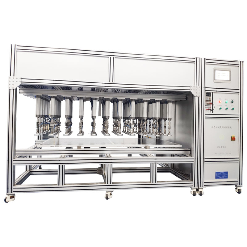
Technical Specifications and Functions
1 Cylinder Type Equipment: Allows the sample module to bend and deform freely when under load, ensuring uniform plane pressure within ±5%
2 Pressurization Method: Gradually increase the load evenly until the set value is reached, both downward and upward pressurization
3 Module Installation: Can meet the requirements of module manufacturers' installation manuals, cylinder spacing adjustable
3.1 The test module includes various types of products, with a maximum installable module size of 2.6m×1.6m, and the module mounting platform should facilitate the installation of various specifications of modules.
3.2 Pneumatic and force feedback methods: Cylinder type and quantity: Low-friction force (cylinder stroke: 400mm)
3.3 Number of cylinders: 84 groups (12*7), allowing for freely adjustable suction cup spacing in both horizontal and vertical directions.
3.4 Installation methods: Pressure block, mounting hole screws, dual-glass fixtures, shared beams, single-axis 2.3.5 Cylinder center point spacing ≤20cm, edge cylinder center distance from module edge ≤20cm
3.6 The sample module can deform freely when under load, and when the module undergoes deformation, the pressure of each suction cup automatically compensates and adjusts, ensuring the uniformity of plane pressure within ±5% during the testing process.
3.7 Deformation measurement: Infrared non-contact, deformation measurement range ±10cm, accuracy ±0.5mm, 5 points in total, can be placed at any position within the same plane.
4 DC Regulated Power Supply (Powering 1 Module): DC Power Supply: 120V5A
5 Software Control:
5.1 Test pressure, cycle times, cycle time, current when powered on, each test parameter of each cycle can be programmed separately: each item of each cycle must be able to set a separate parameter.
5.2 Each suction cup pressure can be controlled separately, and the pressure can be set separately.
5.3 Collect test pressure, time, module deflection, real-time completed cycle times, current when powered on, voltage, module temperature data, collection frequency can be set.
5.4 Touch screen control can be used; the control screen should display real-time test data curves; the control screen should be able to view historical data, curves; historical data can be exported to EXCEL.
6 Static Mechanical Load: Downward pressure 800Pa~12000Pa, upward pull 800Pa~6000Pa, software setting
7 Dynamic Mechanical Load: -2500Pa~+2500Pa, software setting, 3~7 cycles/min
8 Deflection detection: Laser non-contact, measurement range ≥10cm, accuracy ±0.5mm, 5 points in total, can be placed at any position within the same plane.
9 Temperature monitoring: Equipped with a temperature sensor (OMEGA T-type thermocouple), calibration point: 25℃
10 Controller: Can save operation data, with USB interface, can convert operation data to EXCEL/PDF files and charts.
11 Software: Add uneven load software: each cylinder can independently set the pressure.
12 Safety requirements:
12.1 The air source has a safety valve, status indicator, etc. The equipment should alarm and stop testing in case of test failure.
13 Site range: Length 4200mm * Width 2100mm
14 Electrical and gas requirements for the equipment: Power supply requirements: AC220V, 2KW Gas source requirements: 0.6~0.8MPa
