1. DC Constant Current Power Supply: Quantity: 8 channels
Power Supply Brand: Custom-made domestic brand
Option 1: Rated Power/Voltage/Current: 100V/30A
2. Current Switching Function:
① TC200 follows the IEC 61215-2:2021 procedure to automatically switch the current (red line in the following figure):
New Test Condition: A 5 N weight capable of being attached to the electrical termination leads of the module.
Revised Test Condition: at temperature from -40°C to +80°C. During cool down, the -40°C dwell phase and temperatures above 80°C the continuous current shall be reduced to no more than 1.0% of the measured STC peak power current to measure continuity. If the temperature rises too fast (greater than 100°C/h) at the lowest temperature, the start of the current flow can be delayed until the temperature has reached -20°C.
New Voltage Monitoring: In a module with parallel circuits, an open circuit in one branch will cause a discontinuity in the voltage but not cause the current to go to zero.
② HF10 Dampness-Freeze Test: Apply continuous, not exceeding 0.5% STC peak power current through the module.
If 0.5% of the measured STC current is less than 100 mA, then 100 mA may be applied instead.
New Voltage Monitoring: Throughout the test, record the module temperature and monitor the current and voltage through the module.
③ LeTID Light-Induced Degradation Test at High Temperature: Itest = Isc - Imp
④ Option: The following are applicable only to IEC 61215-1-4:2016 CIGS module tests:
- TC100 Thermal Cycling Test:
Apply continuous 10% STC peak power current through the module.
- HF10 Dampness-Freeze Test:
Apply continuous, not exceeding 0.5% STC peak power current through the module.
- DH Damp Heat Test:
Method B: Reverse connection, voltage set to Vmp (±5%) under STC conditions, current limited to 25% of Isc under STC, monitor the direction of module voltage and current.
3. Others:
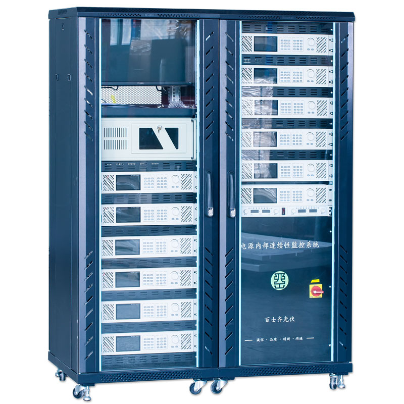
4. Configuration: System configuration includes 1 electrical control cabinet, 1 industrial computer, 8 double-core PV cables with matching standard MC4 connectors, 8 thermocouple wires, and a 5N
functions: Real-time display of current, voltage, and temperature working curves, monitoring, analysis, and display of multiple current, voltage, and temperature channels, and saving collected data in EXCEL format to the database.