1. Technical requirements
Temperature and humidity technical requirements
1) Temperature range: -45-130℃
2) Temperature deviation (in steady state): ≤ ±2°C
3) Temperature uniformity (in steady state): ≤ 2°C
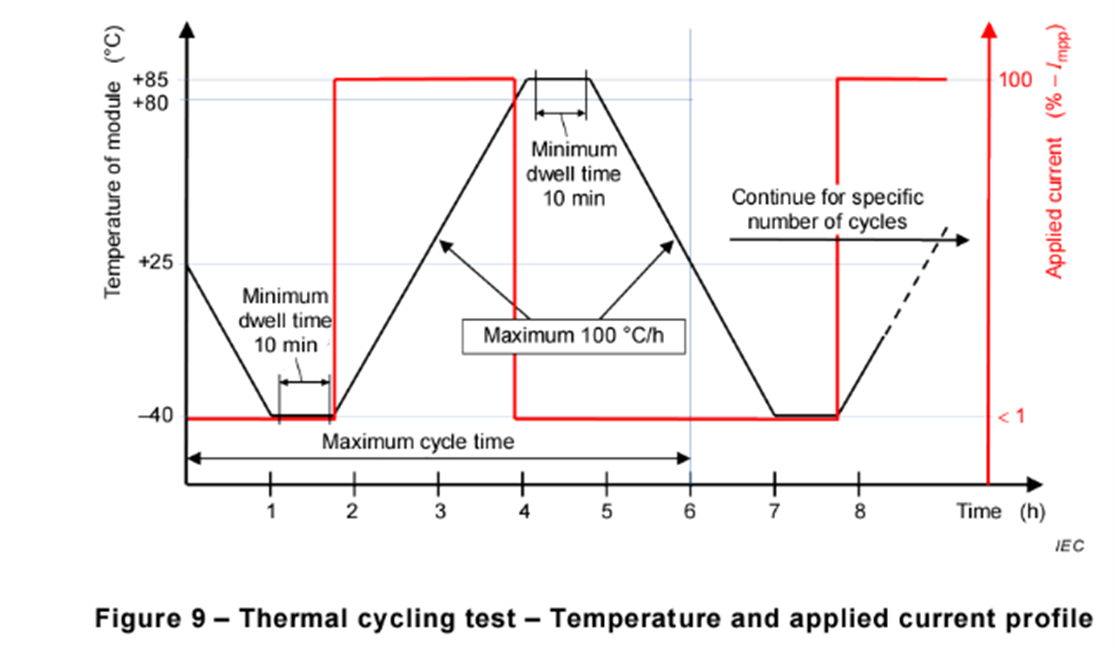
4) Adjustable linear heating rate (from -40°C to +85°C) under full load: 1.5-3.3℃/min
5) Adjustable linear cooling rate (from 85°C to -40°C) under full load: 1.5-3.3℃/min
6) Humidity range: 20% to 98% R.H. (see temperature and humidity range chart below)
7) Humidity deviation (in steady state): ±2.5% RH
8) Temperature range for humidity control: 20°C to 90°C
9) Humidity deviation:
≤ ±2.5% RH (humidity > 75% RH)
≤ ±5.0% RH (humidity ≤ 75% RH)
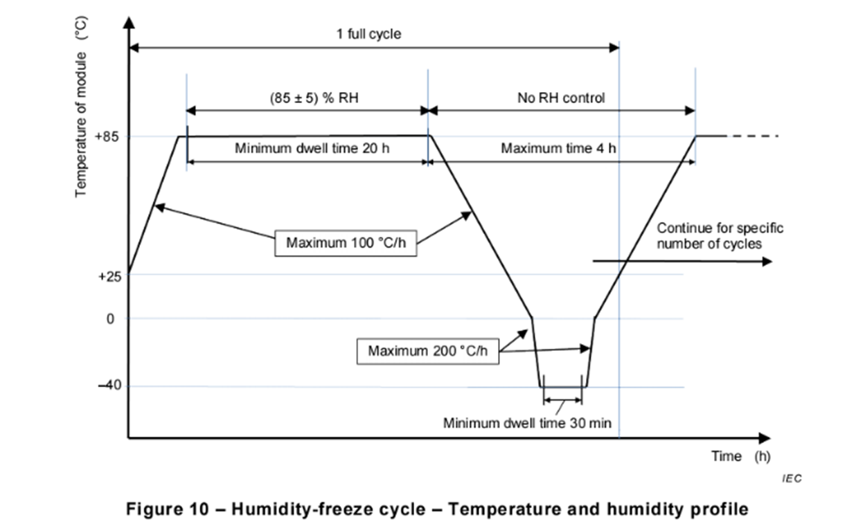
≤ ±2.5% RH (constant at 85℃/85% RH in UL1703 Figure36.1 Humidity-freezing cycle test)
2. Chamber structure
1). Insulation material: Polyurethane foam, insulation thickness ≥ 150mm
2). Inner wall: High-quality heat-resistant and corrosion-resistant SUS304 stainless steel, thickness 2.0mm
3). Outer wall: High-quality A3 steel plate electrostatic spray, steel plate thickness: 1.2mm
4). Inner chamber bottom: High-quality non-slip SUS304 stainless steel patterned plate, thickness 3.0mm
3. Control system
1). Control system: Touch screen display + PLC combination
2). Touch screen size: Not less than 10 inches
3). System setting accuracy: Temperature accuracy: 0.1°C Response time: 1S
4). User program capacity: Programmable quantity greater than 100, each program greater than 999 steps, capable of cycling tests greater than 100 times, and able to link and run programs arbitrarily. Programs can be copied and deleted.
5). Number of cycles: 999 cycles
6). Operation mode: Switch between program operation or constant operation
7). The control system has a self-check function during startup. If there is a malfunction, the equipment cannot start and an error alarm menu will pop up. It also has a timed operation function. As long as the set time is reached, the system will stop automatically.
8). Detailed fault display and alarm. When the test chamber is abnormal, the controller displays the fault status in Chinese characters.
9). Equipped with historical data table trend chart (at least 6 months of retention) and storage function for historical fault records.
10). USB data export function and data analysis
11). LAN network remote monitoring (with host computer software) can be used in conjunction with PID and internal continuity testing system
4. Refrigeration system
German GEA (BOCK) semi-hermetic compressor Quantity: 2 units